A Good Way To Remember Relay Wiring Diagram The same goes for ground power sources too. In a de-energized state, the relay will power a hot power source to the 87a terminal while in an energizing state it will output a hot power source to terminal 87. It will output that power to terminal 87 or 87a of a load wire.įor example, if you give terminal 30 hot power sources. Whichever power source (positive or negative voltage) you give to the common terminal of the high amperage circuit of terminal 30.

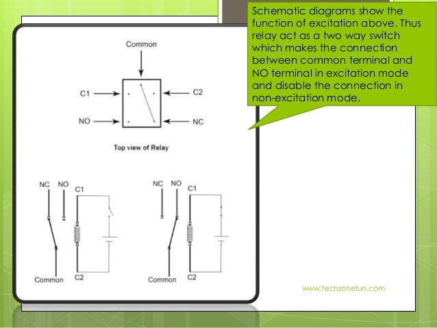
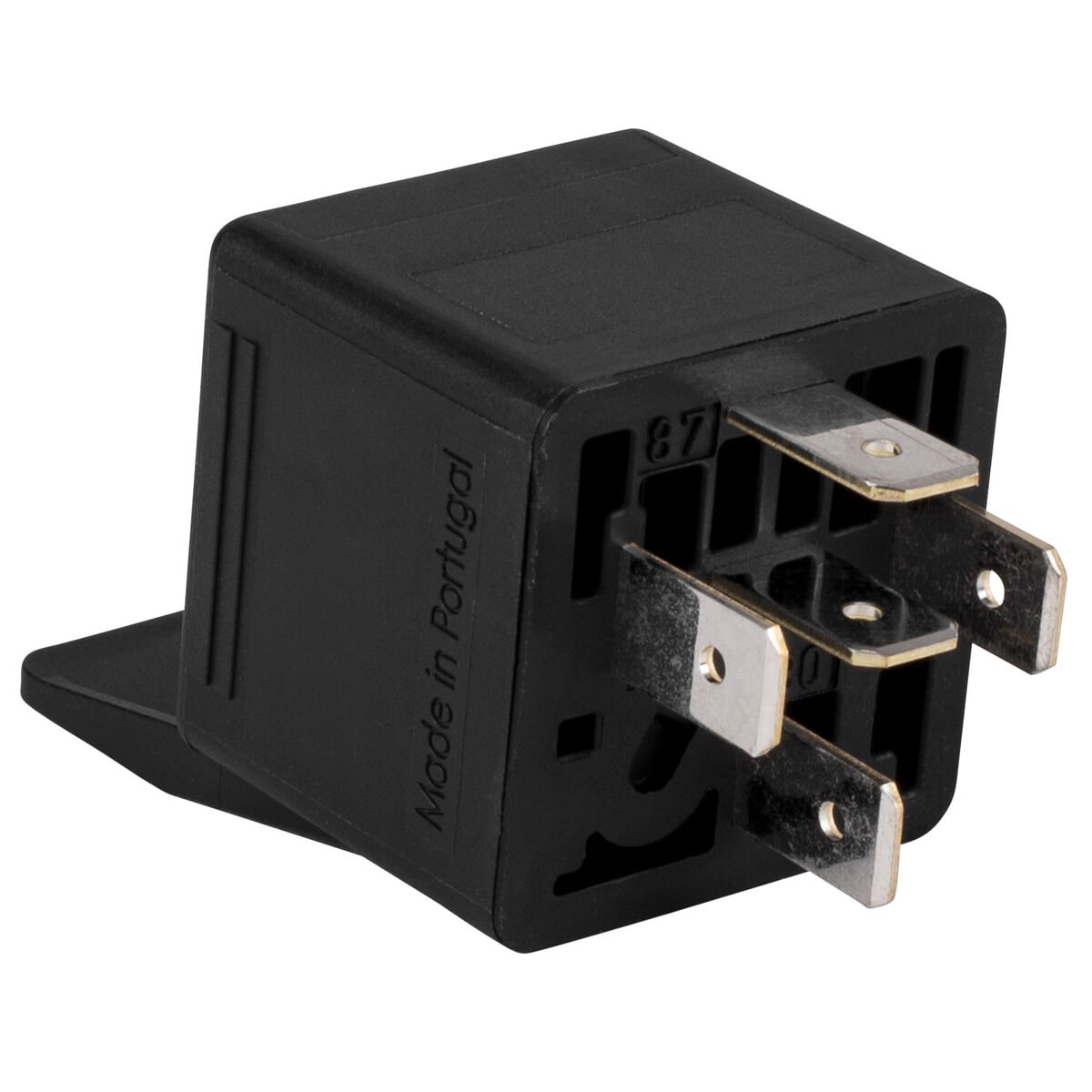
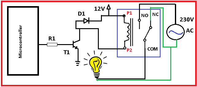
Relay’s high amperage circuit’s terminal 30 is connected with fused wire from the fuse box, while terminal 87 of the high amperage circuit is connected to the horn. The relay coil circuit’s terminal 86 is connected to the battery positive power source, while terminal 85 is connected to the steering wheel horn pad, which is a ground power source. It is used on applications where current is required when the relay is not energized. It means, by default, it lets the current out without energizing the relay and stops the current when the relay is energized. Similarly, terminal 87a is a normally closed contact, and its contacts open when the relay is energized. The power goes out through this terminal to the component when the relay is energized. Terminal 87 is an open contact and always stays open, closes when the relay is energized. Terminal 30 is a common contact, the battery power comes through this terminal to the battery. The five-pin relay’s high amperage circuit consists of three terminals 30, 87, and 87a. The coil circuit’s two wires are terminals 85 and 86, in which terminal 85 is considered negative contact and terminal 86 is considered positive contact. In a five-pin relay, there are five terminals in which two terminals are for the coil circuit, and three terminals are for the high amperage circuit. It is used for circuits that need power when the relay is not activated. It is the extra fifth terminal, which is not commonly used in automotive relays. There is also a third wire that comes in high amperage circuit of a 5 pin relay, which is called terminal 87a. 12-volt power comes to a relay through this terminal (we can say Power-In Wire).Īnd the second wire of high amperage circuit terminal 87 gets power out of the relay and sends it to the component (we can say Power out Wire). Terminal 30 is considered to be a common terminal. Usually, terminal -85 is given a ground power source and terminal +86 is given a hot power source, to make a complete circuit. In a relay 85 and 86 pins are considered coil circuit pins while 30, 87, and 87a pins are considered high amperage circuits.

You need to know that a relay has two circuits, a coil circuit, and a high amperage circuit. Below is the wiring diagram of the four and five-pin car relay.Īccording to DIN 72552 Standard, each pin of a relay is numbered 85, 86, 30, 87, and 87a. Here we will only discuss the relay’s terminals. DIN standardizes almost every terminal in an automobile with code.

#Common pin relay code
The standard code for electrical terminals is known as DIN 72552 standard and is almost accepted throughout the world. The DIN organization also gives a standard DIN code to motor vehicles. This national organization gives standard numbers (Known DIN Standard) to almost every field of technology, covering almost thirty thousand DIN Numbers. It stands for Deutsches Institut für Normung means the German Institute for Standardization. In the last century, Germany made an organization called DIN Standard. Stick with me, here I am giving you a little background about automotive relay terminals. Here in this section, I am explaining the wiring diagram of the four and five-pin car relay. All you need to know is the basics of a car relay wiring diagram. The automotive relay wiring diagram is not complicated, it’s very easy.


 0 kommentar(er)
